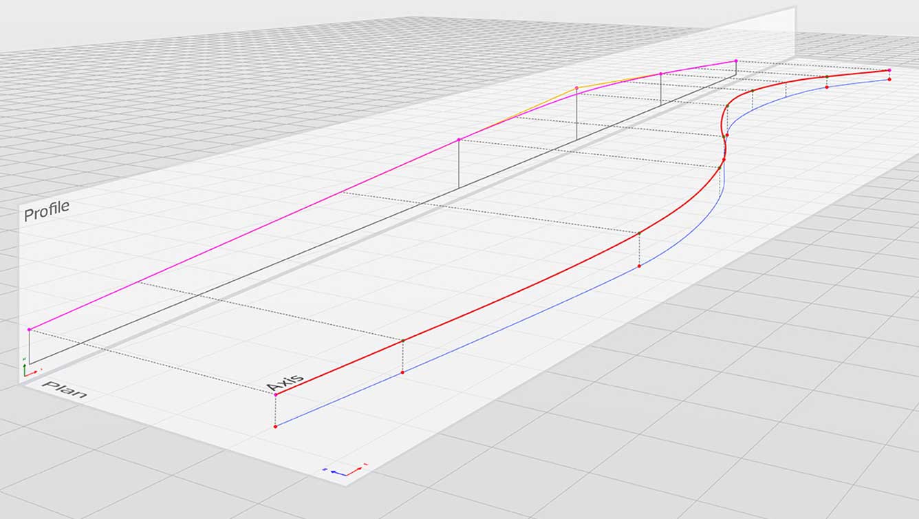
Every bridge construction project starts with one or more axes – with Allplan Bridge, you can adopt the data from an existing design (using LandXML data format) or define it manually. In both cases, the alignment is parametrically saved.
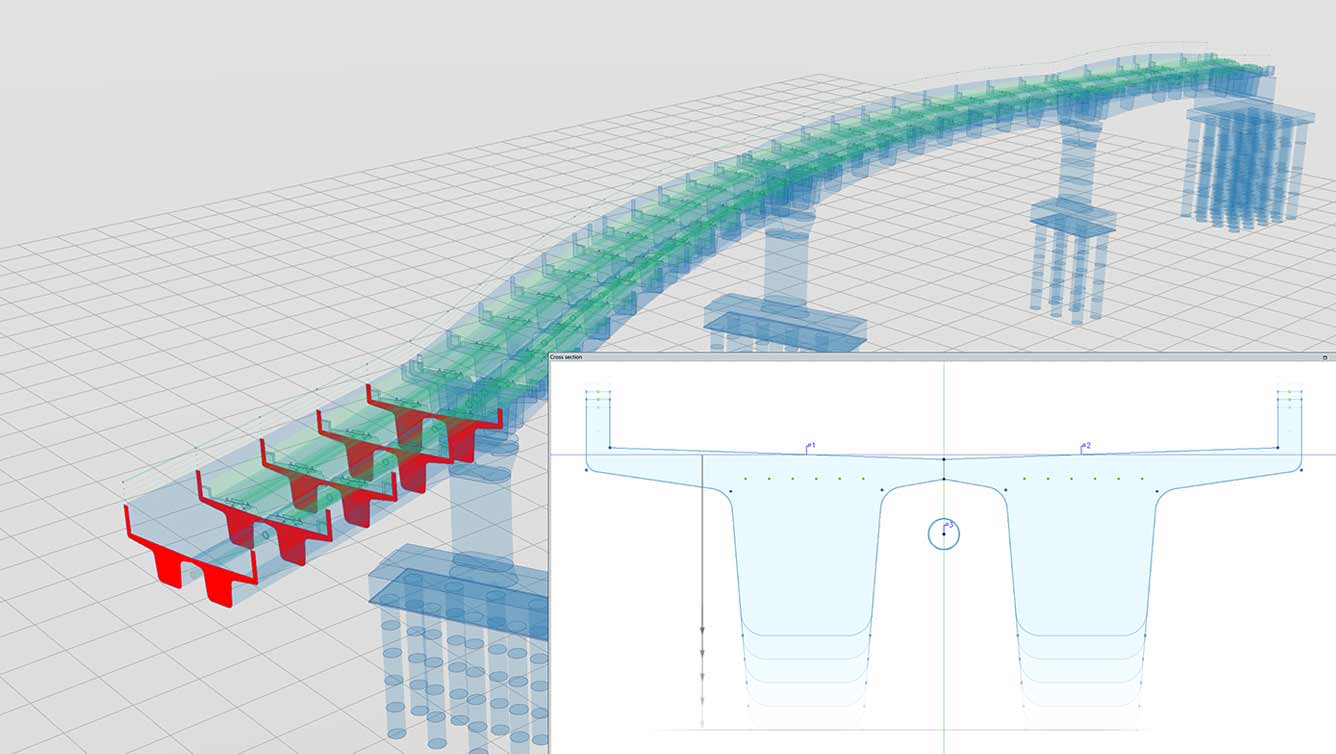
You can define any cross-section and determine the geometry with its dependencies and variables. These parametric cross-sections can be adapted at any time and can be saved as a template and reused.
When defining the cross-section, standardized and repeatedly arranged cross-section parts (like longitudinal stiffeners in steel and composite sections) can be easily placed in the section. The profile can be manually generated in a separate cross section or can be imported from the user section library. Once the profile geometry is defined the position and the number of profiles is set and the product automatically places the profiles along the cross-section edge. The connection between the profile and the cross-section edge is automatically adapted by extruding or trimming the profile
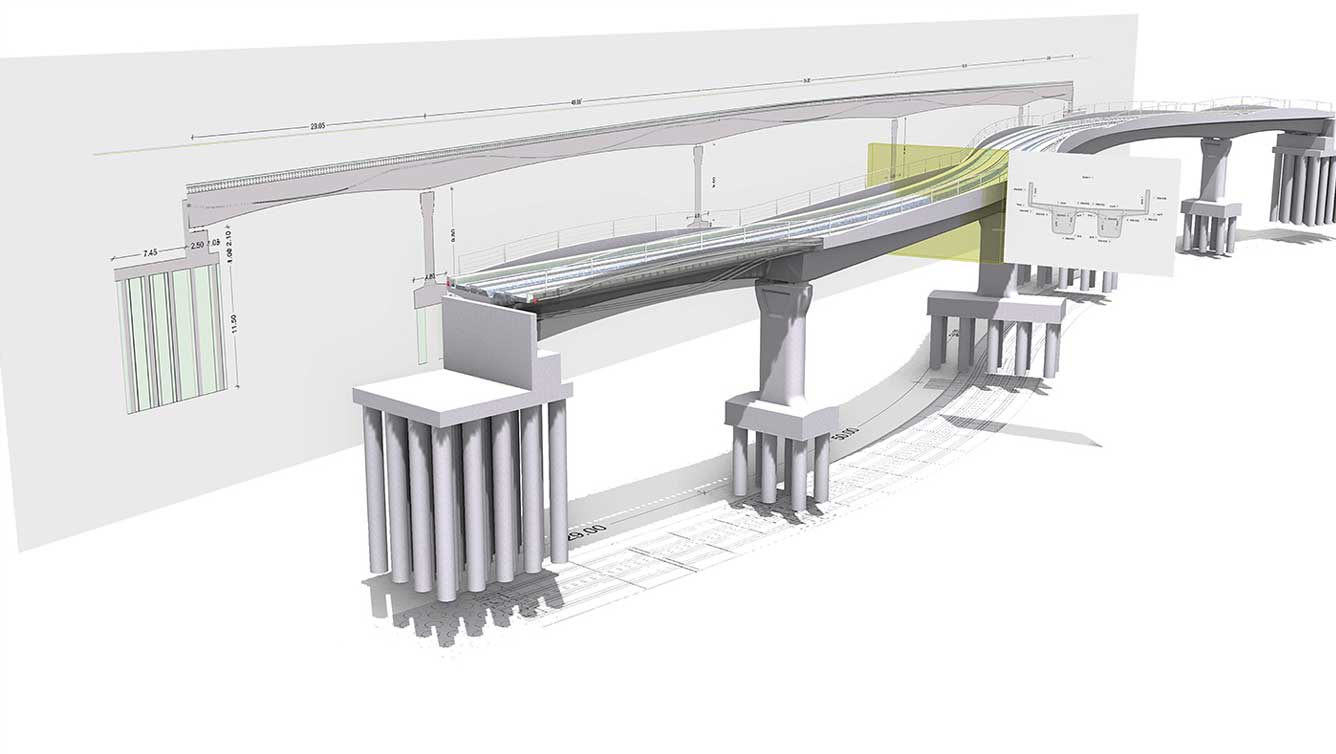
The 3D parametric model description considers the road layout, bridge alignment and required cross-sections, making model configuration quick and efficient.
Complex geometries including double curved alignment and variable cross-sections can be created easily with the help of alphanumeric entries and formulas.
For example, the user only needs to define one typical cross-section and Allplan Bridge will accurately calculate all cross-section variants in accordance with the defined table(s) or/and formula(s). A complete 3D Bridge model cannot be generated more easily or quickly.
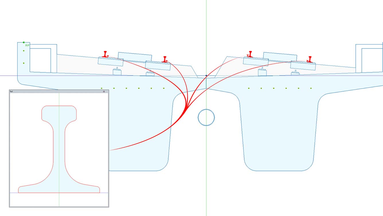
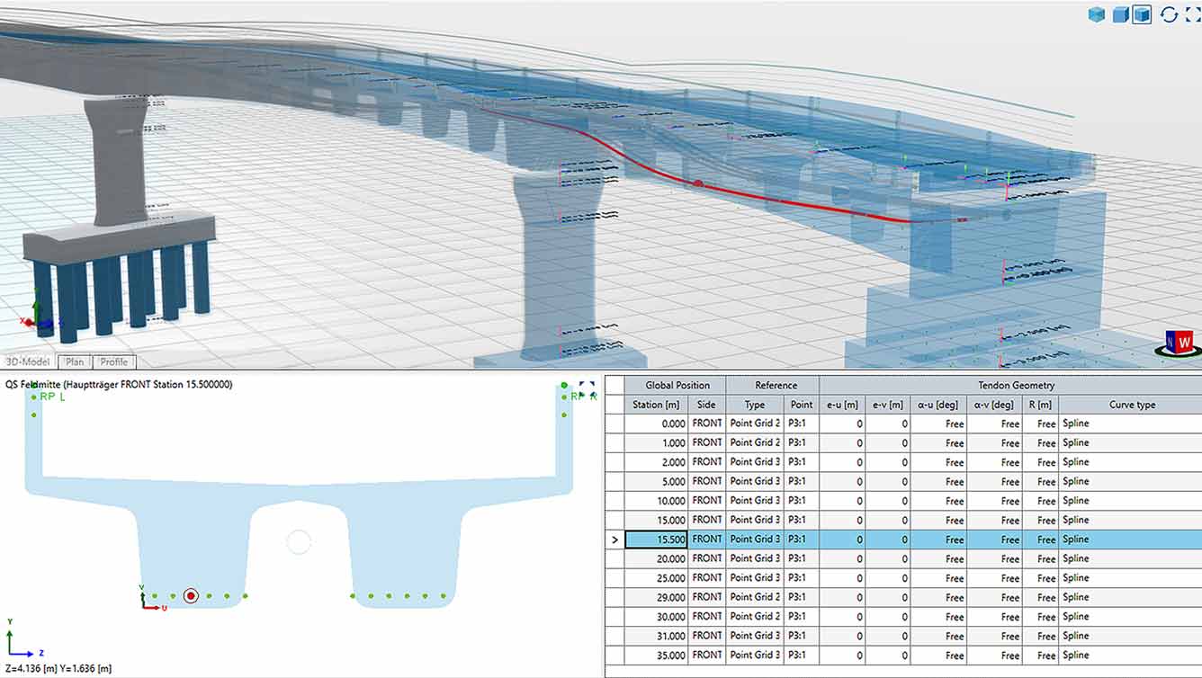
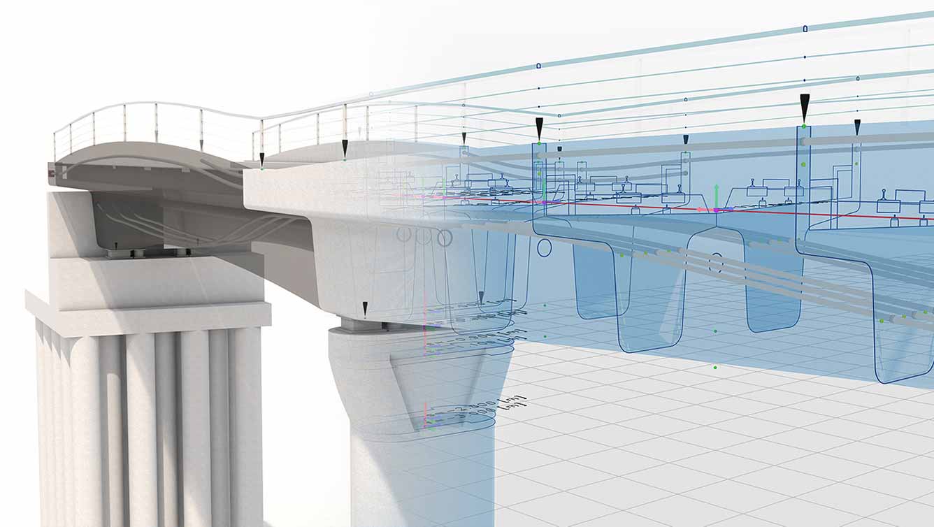
Allplan Bridge 2019 makes it easy to model a wide range of types of pre-stressing: with immediate or later bond, internal and external, longitudinal, transverse and vertical, as well as with non-standard geometry.
Based on user-defined 3D points, the program automatically generates the geometry of a tendon along the bridge structure. Each 3D Tendon point is specified by the position along the axis, and the position in the cross-section in relation to a reference point. In addition, direction angle and curvature radius of the tendon can be specified in each point.
Selective parameters can be defined as variable. When calculating the detailed tendon geometry, the program determines these values automatically, using an intelligent algorithm minimizing the friction losses in the stressing process.
A special point grid is available in the cross-section to ease the specification of the tendon position in the cross-section plane. This point grid facilitates copying and mirroring of the tendon in longitudinal and transverse direction.
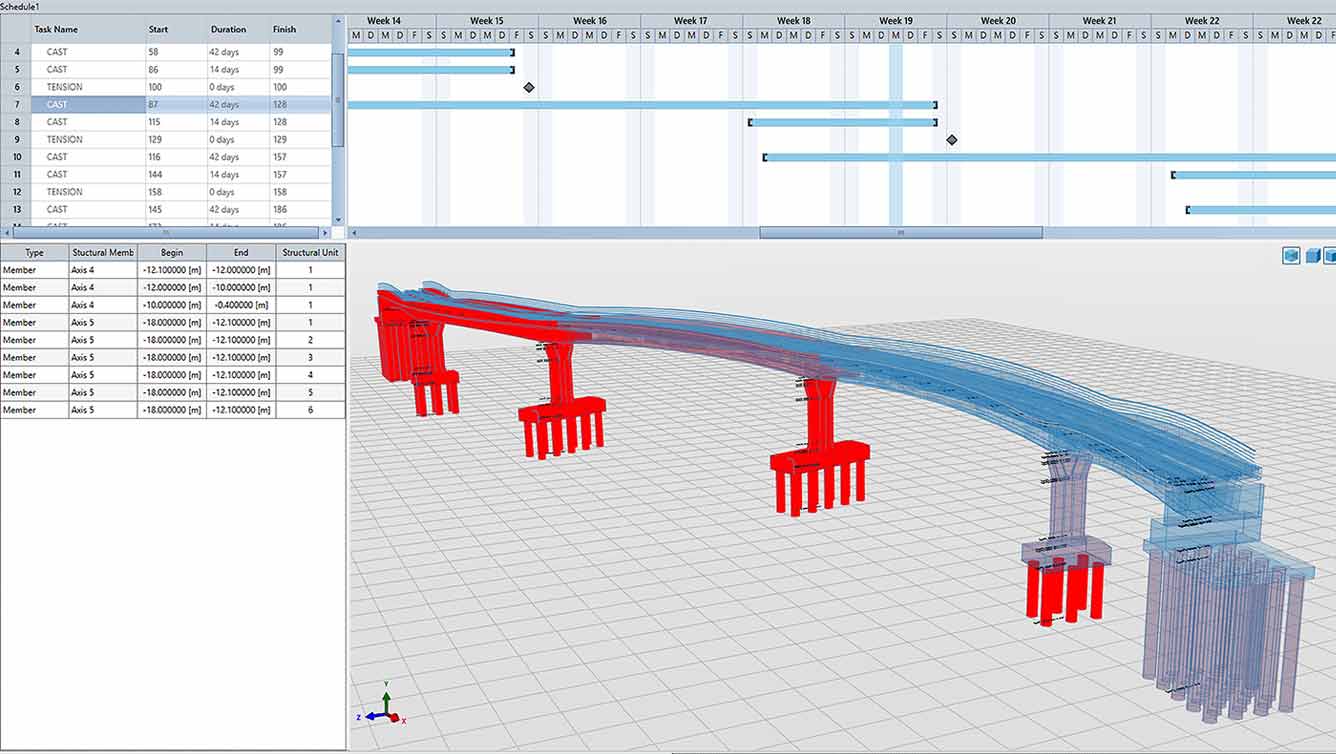
In Allplan Bridge, the time as 4th dimension is considered when specifying the construction process. The construction plan is divided into several phases and further into individual tasks, such as concrete hardening, tendon stressing, activation of self-weight etc.
The begin of a task can be defined as starting date or starting day. The starting day can be defined as global day or relative to the phase begin. The next time attribute that needs to be defined is the duration of the task. In this way the chronological shift of phases and/or tasks is easier, and the user has full control on how this affects previous and subsequent definitions.
The related structural components are interactively assigned to these tasks and this assignment connects the time attributes to the structure.
Furthermore, in Allplan bridge it is possible to define different schedules for the same bridge structure. This allows to analyze different schedule variants and, on this way, to optimize the construction sequence.
Relative definition of start day
Gantt diagram for definition and visualization
Interactive 3D assignment of construction segments
The detailing model subdivide into construction segments automatically
In Allplan Bridge the structural model does not need to be modelled from beginning but the existing geometrical model is used as a basis. With some minor analysis relevant definitions, the geometrical model is complemented, and the analytical model can be generated automatically. This automated process is completely user controlled.
Some of the analysis relevant definition start already in the cross-section definition. By using “Structural units” the user specifies, which bridge parts contribute to the structural system and which need to be considered only as load. Furthermore, it defines into how many beam elements the super- or substructure needs to be subdivided.
One of the additional analysis relevant definition that need to be made is the definition of the degrees of freedom (DOF) of a spring element.
Further analysis relevant definitions need to be specified on the girder level. The element numbers are assigned automatically, and the user must choose only the material.
The analytical model for tendons is also generated from their geometrical geometry. The product analysis the exact position of the tendon relative to the girder and assigns the corresponding beam elements to the tendon automatically.
Automatic or manual numbering of beam elements
Calculation of cross-section properties for arbitrary cross-sections
Semiautomatic generation of grillage model
Analytical 3D tendon element derived from geometrical tendon layout
The product analyses previously defined construction schedule and assembles all necessary calculation definitions in an automated process, like load cases, element activation and calculation actions. This includes input data for calculating nonlinear time effects, creep, shrinkage and relaxation.
All the generated items are listed in “logging” and with that complete transparency is granted. In the list it is possible to see what exactly was generated. The user always keeps full control by adjusting specific tasks in the construction schedule or by deactivating the auto-generation and defining load cases and calculation actions manually.
For example, the action for calculation the nonlinear time effects is automatically generated when concrete elements become active. The time for which the effects need to be calculated is retrieved from the subsequent tasks (when the next structural change happens). Certain additional data is automatically retrieved from the assigned material and other are defined by the user. However, the user can deactivate the auto generation and define the action and all time-dependent definitions manually.
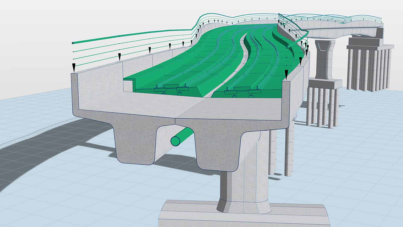
The weight and the position of superimposed dead loads (like sidewalk, road pavement, etc.) are automatically retrieved from the geometrical model. This is done for all structural parts which are marked as load. The product evaluates the area of the equipment and from the assigned material the load intensity is calculated. Once the user specifies the point in time of the equipment installation, the load is applied on the structural system as a uniformly distributed load in the centre of gravity of the equipment.
Additional loads, like temperature change, wind loads, settlement, loads due to braking and acceleration, etc. can be defined and applied easily as well. For this in the construction sequence definition in the final state a specific task – load case needs to be generated and corresponding loads need to be specified. The structural components that need to be loaded are interactively assigned to these tasks and this assignment applies the load on the beam elements.
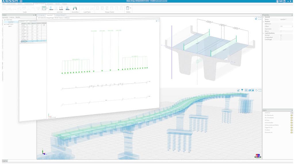
Traffic loads can be defined/applied in a very comfortable way. On the one side, the traffic load is automatically applied in accordance with the selected standard. On the other side, the generic approach of live load definition implemented in Allplan Bridge allows the user to consider any type of moving load.
The definition of the traffic load is split into 2 steps. First the carriageway needs to be split into notional lanes. This can be done manually or automatically. When using the automatic approach, the user needs to select the standard and the parametric lines defining the carriageway. This allows the product to evaluate the number of lanes and their width.
In the second step, the load trains (moving loads) need to be specified. The user can here also manually define an arbitrary train or use the predefined and standard dependent load trains.
As final step, the load trains need to be combined with the corresponding lane. This step also activates the calculation of moving load (influence line evaluation).
The moving load calculation in Allplan Bridge allows for calculating the most unfavorable effects due to traffic. It is based on the theory of (related) influence lines allowing an easy and fast calculation. First the influence lines are calculated by moving a unit force in the defined direction (Vertical, Transversal and Longitudinal) along the corresponding lanes. In the second step the evaluation of influence line is done by placing the load train such that the influence on the respective results becomes a maximum or minimum. Final result of this is an envelope containing the most unfavorable effects. This lane related envelopes must be superimposed with other envelopes to represent the total maxima and minima for further design tasks.
Code dependent design of reinforcement area
Design checks for prestressed and/or reinforced sections
Considering the effects of creep, shrinkage and relaxation
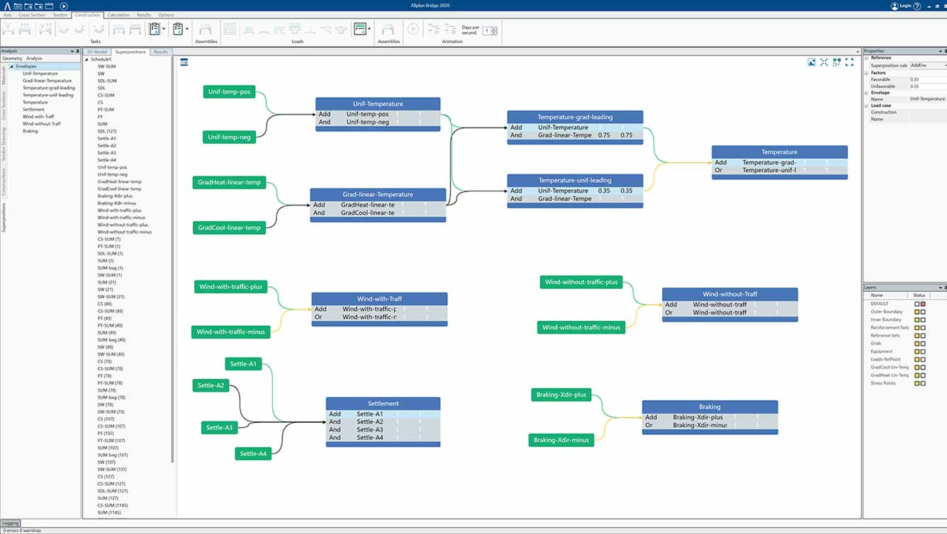
The user-friendliness and usability of the superposition in Allplan Bridge is groundbreaking. The schematic definition of the superposition combines maximum flexibility and optimal overview.
It is possible to select several stress components in user-defined stress points and perform a stress leading superposition. Furthermore, the superposition allows for storing corresponding internal forces between different elements.
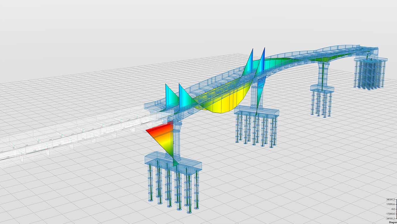
A global static analysis based on the Bernoulli beam theory is performed for all automatically and manually generated calculation actions defined previously in the construction sequence definition. The analysis is enhanced to accurately consider the cross-section variation. Furthermore, the nonlinear calculation of time dependent effects is performed, considering design code formulas.
Analysis model derived from geometrical model
Calculation of construction sequence assembled automatically
Automatic generation of fictitious transversal beam elements for grillage model
Advanced analysis of pre-stressing effects
Calculation of time dependent material behavior (creep, shrinkage and relaxation)
The analysis model automatically derived from the geometrical (architectural) model and the results from the structural analysis are the base for code-based design and checks. Once the relevant envelopes have been created the user can use the code dependent design tasks to determine the required reinforcement content. ULS checks can be performed once the reinforcement content has been calculated or manually specified.
The design of longitudinal reinforcement uses the defined reinforcement position to calculate the necessary area with respect to acting internal forces and certain detailing rules (maximal area and minimal clear space between bars). The procedure enables not only to optimize the reinforcement area for several envelopes, but can also respect the minimum reinforcement area given by the user and add additional reinforcement where needed.
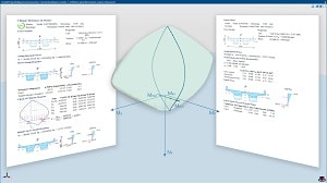
Checks for prestressed and/or reinforced sections can be performed at any time, during the virtual construction process or in the final state, with no limits in section shape and considering the effects of creep, shrinkage and relaxation. Flexure checks are based on the calculated 3D interaction diagram (surface) intersected with the resulting bending moment vector based on the design normal force. The check procedure uses non-linear material stress-strain relationships; so the user can achieve the most economical results.
Code dependent design of reinforcement area
Design checks for prestressed and/or reinforced sections
Considering the effects of creep, shrinkage and relaxation
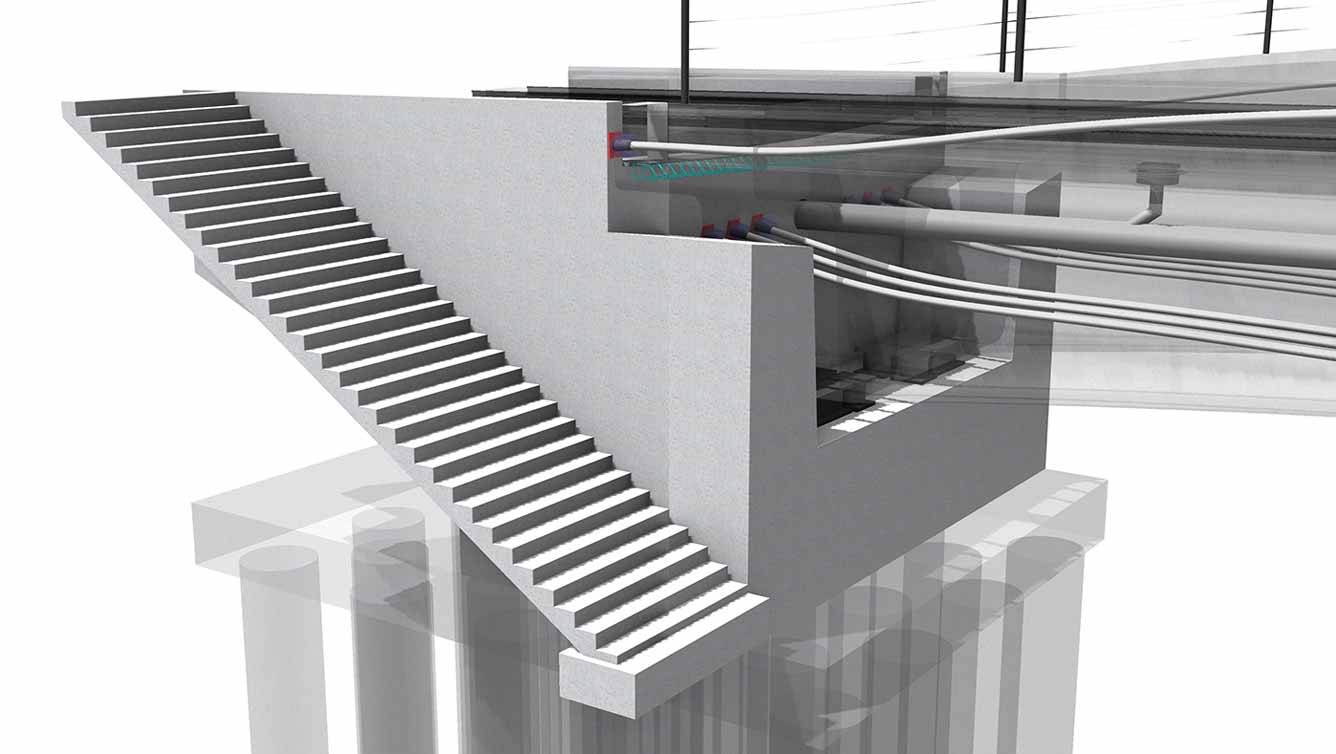
Objects from the Allplan Engineering library can be referenced in Allplan Bridge 2019 to add further details such as lamp posts or anchor devices of tendons to the bridge model. To do this, reference points are defined in Allplan Bridge, using variables along the bridge. These points are linked to the object in the Allplan library using the respective name. When the parametric model is transferred to Allplan Engineering, the corresponding objects are positioned at these reference points. The position of these objects is automatically adjusted whenever the model is updated.
Allplan Bridge helps you to manage the inevitable changes that occur during the design process. The parametric model description is an ideal base for adapting design changes. The modifications are incorporated only at their origin and all other linked members are automatically updated.
For example, if the road axis changes the complete bridge geometry will be adjusted. If only a certain structural member is modified only directly linked elements will be recalculated.
Big advantage of Allplan Bridge is that parallel to the geometrical model also the analytical model automatically updates. This does not only save time but minimizes errors.
Automatic update of geometrical and analytical model
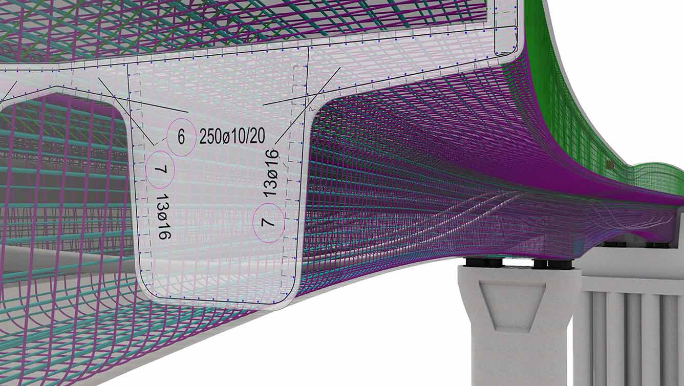
Powerful 3D modeling functionality allows to implement all bridge details without compromise: simply, flexible, and with the highest level of precision. The Parasolid® modeling kernel from Siemens handles intricate free-form geometry based on B-Splines and NURBS as well as for standard tasks such as joints, cut-outs and drainage with ease.
With Allplan, even challenging bridges with double curvature and varying cross-sections are reinforced conveniently and rapidly. The reinforcement is defined in different cross-sections and the transitions between the cross-sections are described with paths. Various rules can be defined, such as how the reinforcement joints are to be carried out. Using this information, the reinforcement is automatically generated.
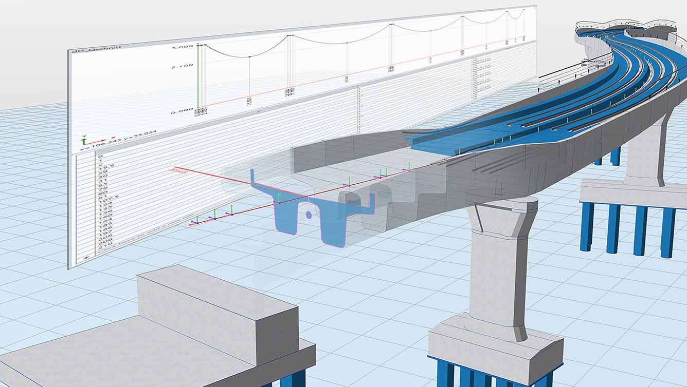
Elevations, longitudinal sections along any path and transverse sections are derived from the digital bridge model. CineRender from Maxon is used for realistic visualizations. Allplan’s powerful layout and design tools are used to create high-quality construction documentation.
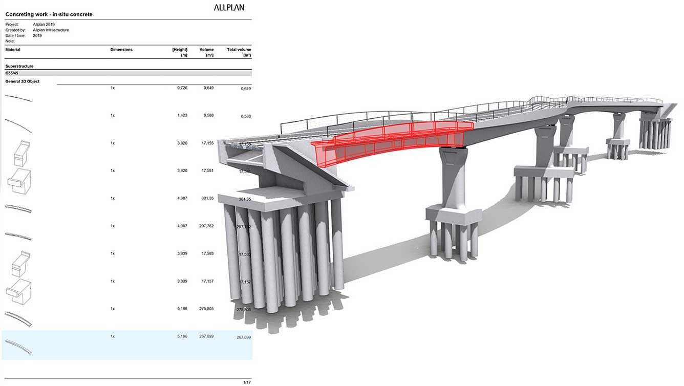
The digital bridge model contains a multitude of information. Comprehensive reports with dimensions, areas, volumes, weights and quantities are available at the touch of a button. This also applies to rebar bending schedules.
Integrating road data used for road/bridge alignment is easily achieved via ALLPLAN’s open BIM platform Allplan Bimplus. The bridge engineer must only take over the road data and can immediately start with the bridge design. To assist the engineer even further, the bridge model can easily be transferred to analysis software (such as Bentley RM Bridge) for structural calculations. Once the design is completed, the parametric model can be transferred in Allplan Engineering for completion of pre-stressing and reinforcement drawings.
The analytical model generated in Allplan Bridge can be uploaded to the cloud-based BIM platform Allplan Bimplus. This allows to transfer the analytical model to other structural analysis solutions connected to Allplan Bimplus.
With the combination of Allplan and the cloud-based BIM platform Allplan Bimplus, everyone involved has access to the latest design, anytime, anywhere and with any device. BIM coordination happens interactively on the digital bridge model. Discrepancies are detected at an early stage and resolved jointly. This is an important contribution to ensuring that the construction project is completed on time and within budget.